



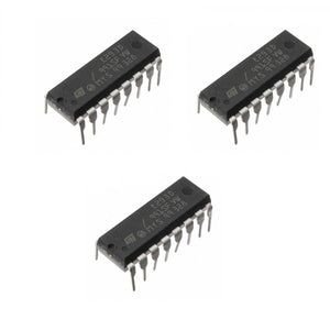
L293D IC Dual H-bridge Motor Driver
Frequently Bought Together
Customers building this project usually buy these together.
Pickup available at Digilog Electronics
Usually ready in 2 hours

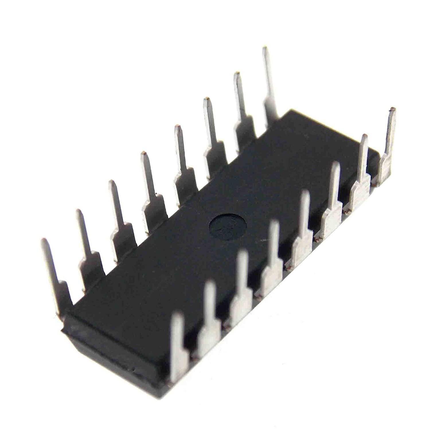
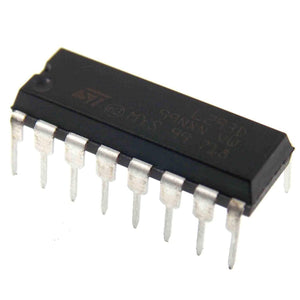
The Device is a monolithic integrated high voltage, high current four channel driver designed to accept standard DTL or TTL logic levels and drive inductive loads (such as relays solenoids, DC and stepping motors) and switching power transistors. To simplify use as two bridges each pair of channels is equipped with an enable input. A separate supply input is provided for the logic, allowing operation at a lower voltage and internal clamp diodes are included. This device is suitable for use in switching applications at frequencies up to 5 kHz. The L293D is assembled in a 16 lead plastic package that has 4 center pins connected together and used for heatsinking.
L293D Pin Configuration
|
Pin Number |
Pin Name |
Description |
|
1 |
Enable 1,2 |
This pin enables the input pin Input 1(2) and Input 2(7) |
|
2 |
Input 1 |
Directly controls the Output 1 pin. Controlled by digital circuits |
|
3 |
Output 1 |
Connected to one end of Motor 1 |
|
4 |
Ground |
Ground pins are connected to ground of circuit (0V) |
|
5 |
Ground |
Ground pins are connected to ground of circuit (0V) |
|
6 |
Output 2 |
Connected to another end of Motor 1 |
|
7 |
Input 2 |
Directly controls the Output 2 pin. Controlled by digital circuits |
|
8 |
Vcc2 (Vs) |
Connected to Voltage pin for running motors (4.5V to 36V) |
|
9 |
Enable 3,4 |
This pin enables the input pin Input 3(10) and Input 4(15) |
|
10 |
Input 3 |
Directly controls the Output 3 pin. Controlled by digital circuits |
|
11 |
Output 3 |
Connected to one end of Motor 2 |
|
12 |
Ground |
Ground pins are connected to ground of circuit (0V) |
|
13 |
Ground |
Ground pins are connected to ground of circuit (0V) |
|
14 |
Output 4 |
Connected to another end of Motor 2 |
|
15 |
Input 4 |
Directly controls the Output 4 pin. Controlled by digital circuits |
|
16 |
Vcc2 (Vss) |
Connected to +5V to enable IC function |
Features
- It can be used to run Two DC motors with the same IC.
- Speed and Direction control is possible
- Motor voltage Vcc2 (Vs): 4.5V to 36V
- Maximum Peak motor current: 1.2A
- Maximum Continuous Motor Current: 600mA
- Supply Voltage to Vcc1(VSS): 4.5V to 7V
- Transition time: 300ns (at 5Vand 24V)
- Automatic Thermal shutdown is available
- Available in 16-pin DIP, TSSOP, SOIC packages
L293D Equivalent Dual Timer IC
LB1909MC, SN754410, ULN2003
Connections with Arduino
- Module 5V (VCC) – Arduino 5V.
- Module GND – Arduino GND.
- Module 1 – Arduino D8.
- Module 2 – Arduino D9.
- Module 3 – Arduino D10.
- Module 4 – Arduino D11.
- Module Motor terminals – DC motors.
- Module VSS power terminal- External power source of 9V.
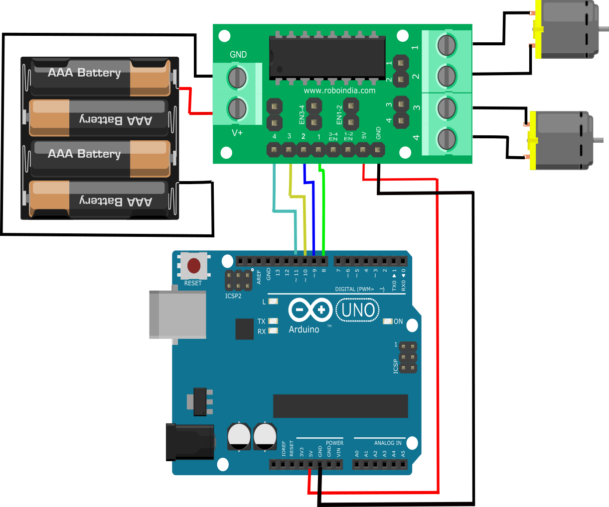
Make the connection as shown above.
Make sure that the Jumpers are preset on the Enable 1-2 and Enable 3-4 pins of module, so that motor will be enabled and work at maximum speed.
2.1. Working Mechanism
Rotation of motor depends on Enable Pins. When Enable 1/2 is HIGH , motor connected to left part of IC will rotate according to following manner:
| Input 1 | Input 2 | Result |
| 0 | 0 | Stop |
| 0 | 1 | Anti Clockwise |
| 1 | 0 | Clockwise |
| 1 | 1 | Stop |
3. Programming:
Here is the code to run this circuit.
//Tutorial by RoboIndia on Motor Control
//Hardware Require: Motor Driver(By RoboIndia) & Arduino

//Motor A
const int inputPin1  = 10;    // Pin 15 of L293D IC
const int inputPin2  = 11;    // Pin 10 of L293D IC
//Motor B
const int inputPin3  = 9;   // Pin  7 of L293D IC
const int inputPin4  = 8;   // Pin  2 of L293D IC


void setup()
{
    pinMode(inputPin1, OUTPUT);
    pinMode(inputPin2, OUTPUT);
    pinMode(inputPin3, OUTPUT);
    pinMode(inputPin4, OUTPUT);
}

void loop()
{
    digitalWrite(inputPin1, HIGH);
    digitalWrite(inputPin2, LOW);
    digitalWrite(inputPin3, HIGH);
    digitalWrite(inputPin4, LOW);
}