

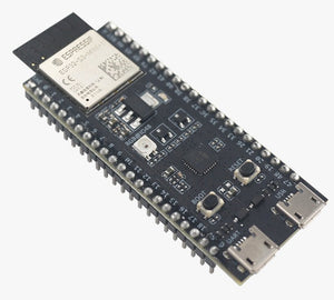
ESP32-S3-DevKitM-1U-N8 Development Board
ESP32-S3-DevKitM-1
This user guide will help you get started with ESP32-S3-DevKitM-1 and will also provide more in-depth information.
The ESP32-S3-DevKitM-1 is an entry-level development board equipped with either ESP32-S3-MINI-1 or ESP32-S3-MINI-1U, a module named for its small size. This board integrates complete Wi-Fi and Bluetooth® Low Energy functions.
Most of the I/O pins on the module are broken out to the pin headers on both sides of this board for easy interfacing. Developers can either connect peripherals with jumper wires or mount ESP32-S3-DevKitM-1 on a breadboard.
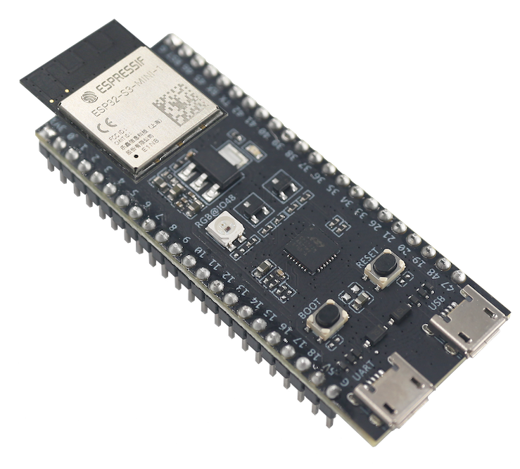
ESP32-S3-DevKitM-1 with ESP32-S3-MINI-1 Module
The document consists of the following major sections:
-
Getting Started: Overview of the board and hardware/software setup instructions to get started.
-
Hardware Reference: More detailed information about the board’s hardware.
-
Related Documents: Links to related documentation.
Getting Started
This section provides a brief introduction of ESP32-S3-DevKitM-1, instructions on how to do the initial hardware setup and how to flash firmware onto it.
Description of Components
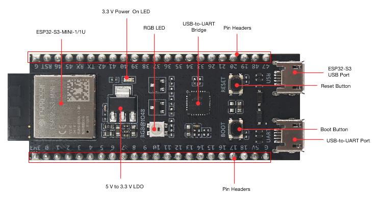
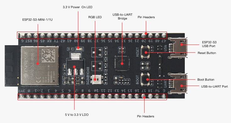
ESP32-S3-DevKitM-1 - front
The key components of the board are described in a counter-clockwise direction, starting from the ESP32-S3-MINI-1/1U module.
|
Key Component |
Description |
|---|---|
|
ESP32-S3-MINI-1/1U |
ESP32-S3-MINI-1 and ESP32-S3-MINI-1U are two general-purpose Wi-Fi and Bluetooth Low Energy combo modules that have a rich set of peripherals. ESP32-S3-MINI-1 comes with a PCB antenna. ESP32-S3-MINI-1U comes with an external antenna connector. At the core of the modules is ESP32-S3FN8, a chip equipped with an 8 MB flash. Since flash is packaged in the chip, rather than integrated into the module, ESP32-S3-MINI-1/1U has a smaller package size. |
|
5 V to 3.3 V LDO |
Power regulator that converts a 5 V supply into a 3.3 V output. |
|
Pin Headers |
All available GPIO pins (except for the SPI bus for flash) are broken out to the pin headers on the board for easy interfacing and programming. For details, please see Header Block. |
|
USB-to-UART Port |
A Micro-USB port used for power supply to the board, for flashing applications to the chip, as well as for communication with the chip via the on-board USB-to-UART bridge. |
|
Boot Button |
Download button. Holding down Boot and then pressing Reset initiates Firmware Download mode for downloading firmware through the serial port. |
|
Reset Button |
Press this button to restart ESP32-S3. |
|
ESP32-S3 USB Port |
ESP32-S3 full-speed USB OTG interface, compliant with the USB 1.1 specification. The interface is used for power supply to the board, for flashing applications to the chip, for communication with the chip using USB 1.1 protocols, as well as for JTAG debugging. |
|
USB-to-UART Bridge |
Single USB-to-UART bridge chip provides transfer rates up to 3 Mbps. |
|
RGB LED |
Addressable RGB LED, driven by GPIO48. |
|
3.3 V Power On LED |
Turns on when the USB power is connected to the board. |
Start Application Development
Before powering up your board, please make sure that it is in good condition with no obvious signs of damage.
Required Hardware
-
ESP32-S3-DevKitM-1
-
USB 2.0 cable (Standard-A to Micro-B)
-
Computer running Windows, Linux, or macOS
Note
Be sure to use an appropriate USB cable. Some cables are for charging only and do not provide the needed data lines nor work for programming the boards.
Hardware Setup
Connect the board with the computer using USB-to-UART Port or ESP32-S3 USB Port. In subsequent steps, USB-to-UART Port will be used by default.
Software Setup
Please proceed to Get Started, where Section Installation will quickly help you set up the development environment and then flash an application example onto your board.
Contents and Packaging
Retail Orders
If you order a few samples, each board comes in an individual package in either antistatic bag or any packaging depending on your retailer.
For retail orders, please go to https://www.espressif.com/en/contact-us/get-samples.
Wholesale Orders
If you order in bulk, the boards come in large cardboard boxes.
For wholesale orders, please go to https://www.espressif.com/en/contact-us/sales-questions.
Hardware Reference
Block Diagram
The block diagram below shows the components of ESP32-S3-DevKitM-1 and their interconnections.
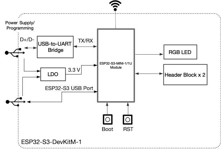
ESP32-S3-DevKitM-1 (click to enlarge)
Power Supply Options
There are three mutually exclusive ways to provide power to the board:
-
USB-to-UART Port and ESP32-S3 USB Port (either one or both), default power supply (recommended)
-
5V and G (GND) pins
-
3V3 and G (GND) pins
Header Block
The two tables below provide the Name and Function of the pins on both sides of the board (J1 and J3). The pin names are shown in ESP32-S3-DevKitM-1 - front. The numbering is the same as in the Board Schematic (PDF).
J1
|
No. |
Name |
Type 1 |
Function |
|---|---|---|---|
|
1 |
3V3 |
P |
3.3 V power supply |
|
2 |
0 |
I/O/T |
RTC_GPIO0, GPIO0 |
|
3 |
1 |
I/O/T |
RTC_GPIO1, GPIO1, TOUCH1, ADC1_CH0 |
|
4 |
2 |
I/O/T |
RTC_GPIO2, GPIO2, TOUCH2, ADC1_CH1 |
|
5 |
3 |
I/O/T |
RTC_GPIO3, GPIO3, TOUCH3, ADC1_CH2 |
|
6 |
4 |
I/O/T |
RTC_GPIO4, GPIO4, TOUCH4, ADC1_CH3 |
|
7 |
5 |
I/O/T |
RTC_GPIO5, GPIO5, TOUCH5, ADC1_CH4 |
|
8 |
6 |
I/O/T |
RTC_GPIO6, GPIO6, TOUCH6, ADC1_CH5 |
|
9 |
7 |
I/O/T |
RTC_GPIO7, GPIO7, TOUCH7, ADC1_CH6 |
|
10 |
8 |
I/O/T |
RTC_GPIO8, GPIO8, TOUCH8, ADC1_CH7, SUBSPICS1 |
|
11 |
9 |
I/O/T |
RTC_GPIO9, GPIO9, TOUCH9, ADC1_CH8, FSPIHD, SUBSPIHD |
|
12 |
10 |
I/O/T |
RTC_GPIO10, GPIO10, TOUCH10, ADC1_CH9, FSPICS0, FSPIIO4, SUBSPICS0 |
|
13 |
11 |
I/O/T |
RTC_GPIO11, GPIO11, TOUCH11, ADC2_CH0, FSPID, FSPIIO5, SUBSPID |
|
14 |
12 |
I/O/T |
RTC_GPIO12, GPIO12, TOUCH12, ADC2_CH1, FSPICLK, FSPIIO6, SUBSPICLK |
|
15 |
13 |
I/O/T |
RTC_GPIO13, GPIO13, TOUCH13, ADC2_CH2, FSPIQ, FSPIIO7, SUBSPIQ |
|
16 |
14 |
I/O/T |
RTC_GPIO14, GPIO14, TOUCH14, ADC2_CH3, FSPIWP, FSPIDQS, SUBSPIWP |
|
17 |
15 |
I/O/T |
RTC_GPIO15, GPIO15, U0RTS, ADC2_CH4, XTAL_32K_P |
|
18 |
16 |
I/O/T |
RTC_GPIO16, GPIO16, U0CTS, ADC2_CH5, XTAL_32K_N |
|
19 |
17 |
I/O/T |
RTC_GPIO17, GPIO17, U1TXD, ADC2_CH6 |
|
20 |
18 |
I/O/T |
RTC_GPIO18, GPIO18, U1RXD, ADC2_CH7, CLK_OUT3 |
|
21 |
5V |
P |
5 V power supply |
|
22 |
G |
G |
Ground |
J3
|
No. |
Name |
Type |
Function |
|---|---|---|---|
|
1 |
G |
G |
Ground |
|
2 |
RST |
I |
EN |
|
3 |
46 |
I/O/T |
GPIO46 |
|
4 |
45 |
I/O/T |
GPIO45 |
|
5 |
RX |
I/O/T |
U0RXD, GPIO44, CLK_OUT2 |
|
6 |
TX |
I/O/T |
U0TXD, GPIO43, CLK_OUT1 |
|
7 |
42 |
I/O/T |
MTMS, GPIO42 |
|
8 |
41 |
I/O/T |
MTDI, GPIO41, CLK_OUT1 |
|
9 |
40 |
I/O/T |
MTDO, GPIO40, CLK_OUT2 |
|
10 |
39 |
I/O/T |
MTCK, GPIO39, CLK_OUT3, SUBSPICS1 |
|
11 |
38 |
I/O/T |
GPIO38, FSPIWP, SUBSPIWP |
|
12 |
37 |
I/O/T |
SPIDQS, GPIO37, FSPIQ, SUBSPIQ |
|
13 |
36 |
I/O/T |
SPIIO7, GPIO36, FSPICLK, SUBSPICLK |
|
14 |
35 |
I/O/T |
SPIIO6, GPIO35, FSPID, SUBSPID |
|
15 |
34 |
I/O/T |
SPIIO5, GPIO34, FSPICS0, SUBSPICS0 |
|
16 |
33 |
I/O/T |
SPIIO4, GPIO33, FSPIHD, SUBSPIHD |
|
17 |
26 |
I/O/T |
SPICS1, GPIO26 |
|
18 |
21 |
I/O/T |
RTC_GPIO21, GPIO21 |
|
19 |
20 |
I/O/T |
RTC_GPIO20, GPIO20, U1CTS, ADC2_CH9, CLK_OUT1, USB_D+ |
|
20 |
19 |
I/O/T |
RTC_GPIO19, GPIO19, U1RTS, ADC2_CH8, CLK_OUT2, USB_D- |
|
21 |
48 |
I/O/T |
SPICLK_N, GPIO48, SUBSPICLK_N_DIFF, RGB LED |
|
22 |
47 |
I/O/T |
SPICLK_P, GPIO47, SUBSPICLK_P_DIFF |
- 1
-
P: Power supply; I: Input; O: Output; T: High impedance.
For description of function names, please refer to ESP32-S3 Datasheet (PDF).
Pin Layout
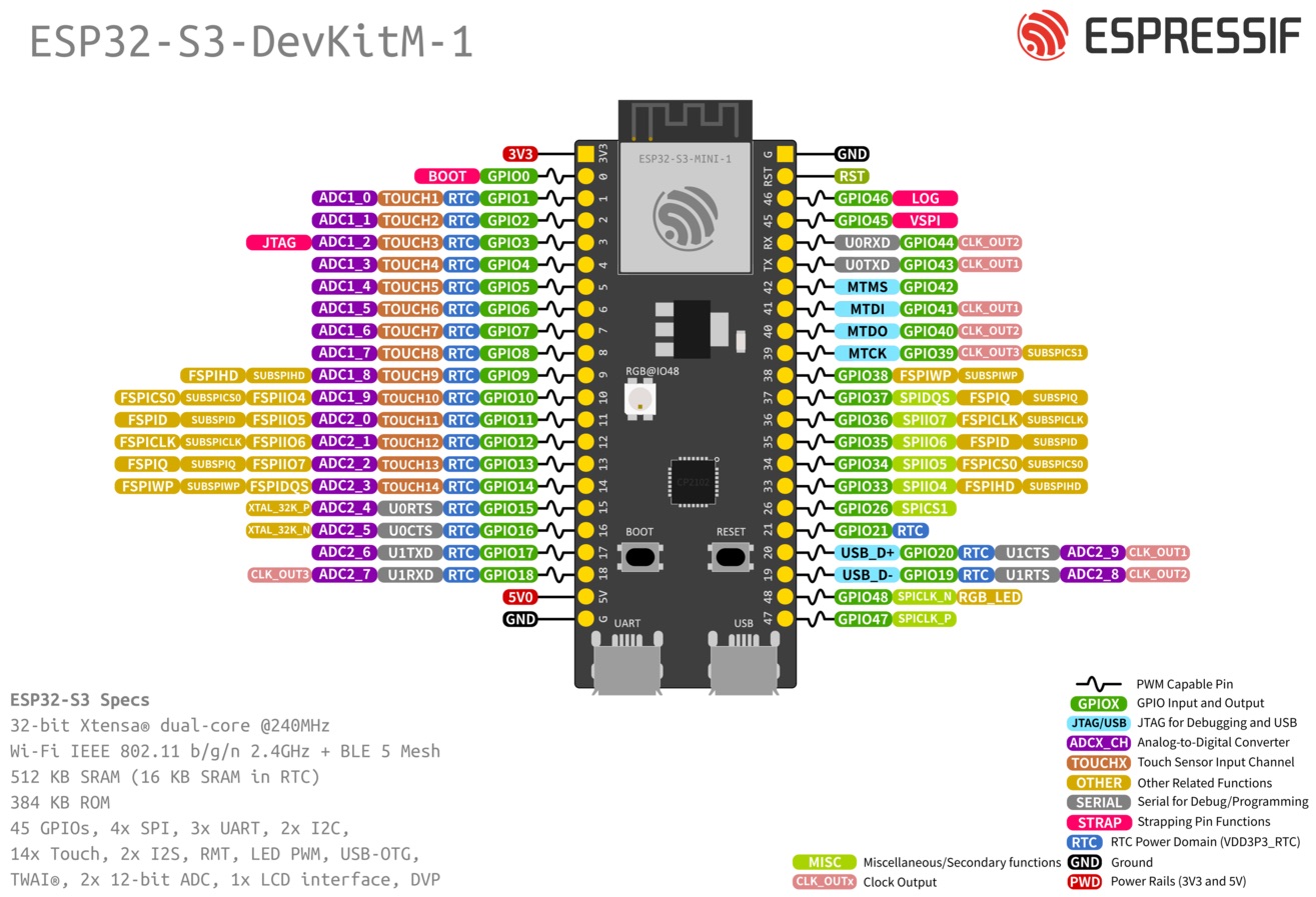
ESP32-S3-DevKitM-1 Pin Layout (click to enlarge)