

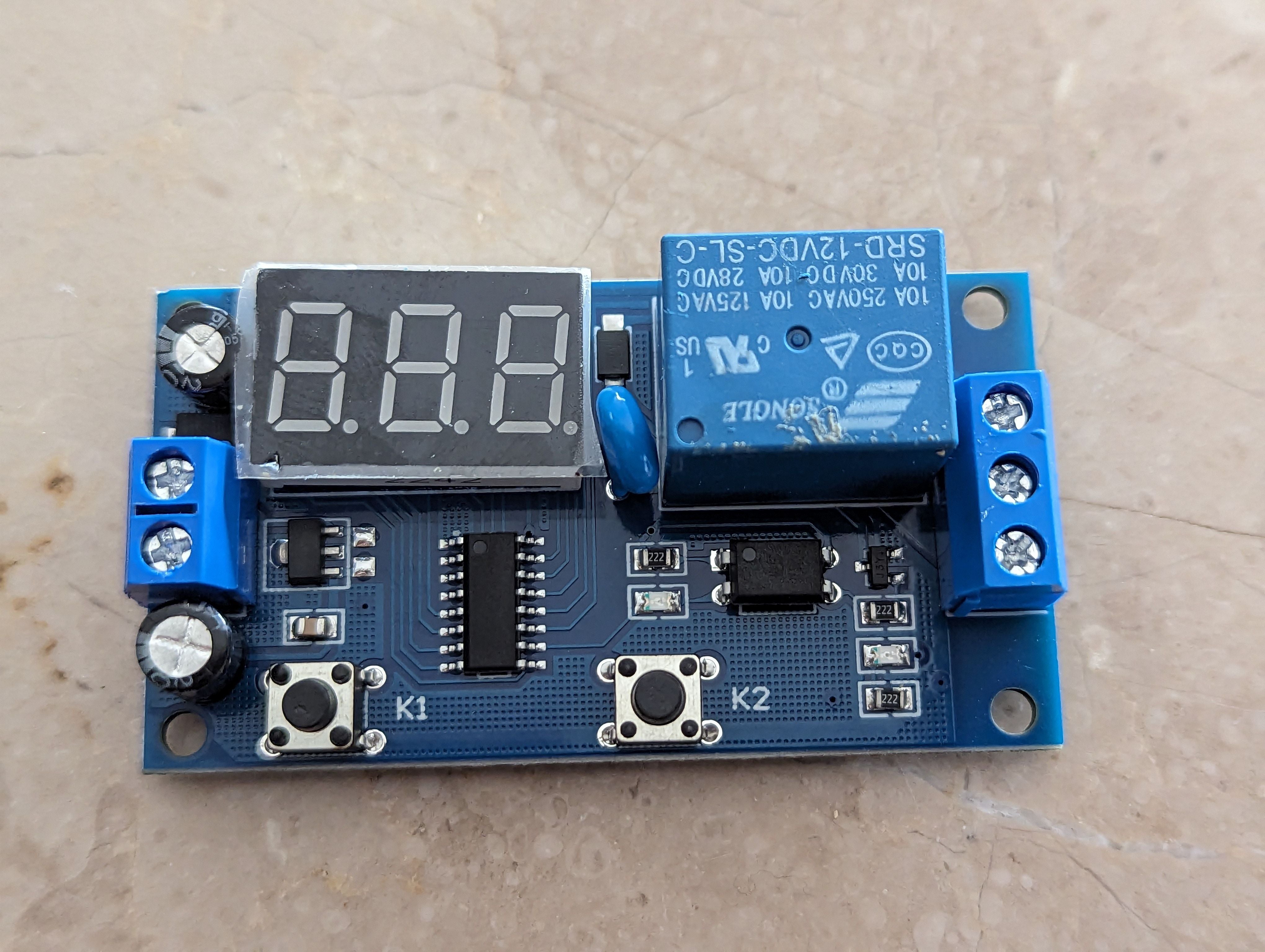



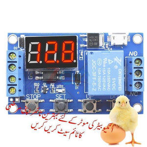
Digital LED Display Programmable Circuit Egg Incubator Timer Relay Module Controller WS16
Frequently Bought Together
Customers building this project usually buy these together.
Pickup available at Digilog Electronics
Usually ready in 2 hours

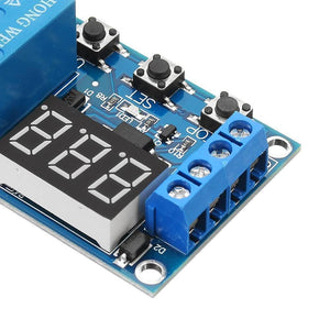
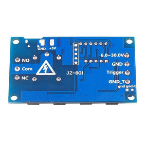
Digital Incubator Timer Relay is a timer relay suitable for your incubator and other time-related projects. The timer relay module is a Digital display Led Home Automation Delay Timer Control Switch Module Timer Controller, Operating voltage: 6-30V, support micro USB 5.0V power supply, Output capability: Can control the device within DC 30V 5A or AC 220V 5A. This best incubator timer controller can be applied to many fields; there is a wide range of applications. Programmable Triggered Timing Circuit board 35238mp.
Features Of 35238mp HW-521 Circuit Incubator Egg Turner Timer Relay Switch Control Module:
- Wide voltage power supply (6 ~ 30V), supports micro USB 5.0V power supply, easy to use;
- The interface is clean, simple, powerful, and easy to understand, can meet almost all your needs;
- With emergency stop function (“STOP” button) and reverse polarity protection which can avoid burning by reverse connection.
- Adding sleeping mode, when the mode is enabled, if there is no operation within 5 minutes, the display will be turned off automatically, press any button will wake it up;
- You can set different parameters of OP, CL, LOP, which are independent of each other and are stored separately;
- All the parameter settings will be stored automatically when power is off.
Specifications Of Timer circuit Incubator Egg turner 6-30V Relay Module Switch Trigger Time Circuit Timer Cycle Adjustable:
- Operating voltage: 6-30V, support micro USB 5.0V power supply
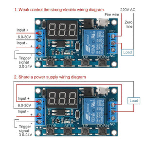
- Trigger signal source: Active-high (3.0V-24V), have optocoupler isolation, can improve the system's anti-jamming capability (customers can also short common ground).
- Output capability: Can control the device within DC 30V 5A or AC 220V 5A.
- Quiescent current: 20mA;
- Operating current: 50mA
- Service life: more than 10 million times
- Working temperature: -40°c ~ 85 °c
- Dimension: 62×38×17mm.
- With optocoupler isolation, enhanced anti-jamming capability, industrial-grade board. The parameter setting will be stored forever when power is off.
- Special Note: The output of the replay is passive contact, without voltage output, just for controlling the on or off of a single circuit.
-
Timing range
- 0.1 seconds (min.) to 999 minutes (max.) continuously adjustable
- How do choose the time range?
- After setting the parameter values in the mode selection interface, you can choose the timing range by short pressing the "STOP" button;
- XXX. the decimal point is in the unit digit, timing range: 1 second to 999 seconds.
- XX. X decimal point is in the tens digit, timing range: 0.1 seconds to 99.9 seconds
- X. X. X. decimal all light on, timing range: 1 minute to 999 minutes.
- For example, if you want to set the "OP" time to 3.2 seconds, you can move the decimal point to the place of tens digit, the digital display 03.2
Operating Mode:
- P1: Trigger signal, the relay is on "OP" time, and then disconnect; Within the "OP" time, proceed as follows:
- P1.1: signal is triggered again, invalid
- P1.2: signal is triggered again, re-clocking
- P1.3: Signal has triggered again, the relay is disconnected, stop the clock;
- P-2: Trigger signal, after the "CL" time is off, the "OP" time is on. When the timing is completed, the replay will be disconnected;
- P3.1: Trigger signal, after the "OP" time is on, the "CL" time is off, then cycle the above actions. If the trigger signal is within the loop, the relay will be disconnected and stop the clock. The number of cycles ( "LOP ") can be set.
- P3.2: No need to trigger the signal after powering up, the "OP" time is on, the "CL" time is off, then cycle the above actions; The number of cycles ( "LOP ") can be set.
- P-4: Signal holding function. If the signal is triggered, timing is cleared, the relay remains on; when the signal disappears, the relay will be off when the "OP" time is over; if another signal is triggered during timing, timing will be cleared.
Parameter Instruction:
- "OP" - On-time
- "CL" - Off-time
- "LOP" - The number of cycles (1-999 times, "---" represents infinite cycles).
- These parameters are independent but are shared by each mode. For example, in P1.1 mode, the on-time "OP" is set 5 seconds. If you switch to P1.2 mode, the "OP" time of P1.2 mode will be 5 seconds too.
- In the main interface (display 000), short press the "SET" button, it will display "OP" ( "CL", "LOP") and the corresponding time XXX;
- If there is only "OP" time in some modes (such as the mode P1.1, P1.2, P1.3), short press the "SET" button to display the “OP” and the corresponding time only;
- There are "OP", "CL", "LOP" in some modes (such as the mode P3.1, P3.2), short press "SET" button will display "OP" and the corresponding time, “CL” and the corresponding time, “LOP” and the corresponding number of times;
- After setting the mode, short press the "SET" button can check all the set parameters of the mode at present in the main interface, easy and convenient!
- How to set parameters?
- 1. Determine the operating mode of the relay.
- 2. The current operating mode (P1.1 mode in default) will flash when the module is powered up. Then enter into the main interface. In the main interface, long-press the "SET" button for 2 seconds then release to enter the mode selection interface, short press the "UP" or "DOWN" button to select the mode (P1.1 ~ P-4) you need.
- 3. After selecting the operating mode (e.g. P3.2), short press the "SET" button to select the parameter to be set. The selected parameter will flash ( "OP" on-time, "CL" off-time, "LOP" cycle times ( "---" represents infinite cycles)), then you can adjust the values by "UP", "DOWN" button to adjust the parameter value, support long press (rapid increase or decrease) and short press (increase or decrease one unit). After finishing adjusting, short press the "STOP" button to select the position of the decimal point, select the timing range (0.1 seconds to 999 minutes). Then short press the "SET" button to enter to set the value of the next parameters. The setting procedure is the same as above.
- 4. After setting the parameters, long-press the "SET" button for 2 seconds then release, the name of the current mode will flash, and then return to the main interface. The parameters setting is completed.
- The main interface: In the status that the relay is not working, the main interface will display "000" (no decimal point); in the status that the relay is working, there will be a decimal point.
- Mode selection interface: Long press the "SET" button to enter into the mode selection interface, after the setting is completed, long-press the "SET" button to exit and return to the main screen.
"STOP" button extensions:
-
Relays enable mode:
- 1. ON: Relay allows conduction in "OP" on-time;
- 2. of relay prohibits conduction and is always closed;
- In the main interface, short press the "STOP" button to switch between ON and OFF, the current status will flash, and then return to the main interface. (This is an emergency stop function, turn off the relay with one button)
-
Sleeping mode:
- 1. "C-P" sleeping mode: If there is no operation in 5 minutes, the digital display will turn off automatically but the program will run as usual;
- 2. "O-d" normal mode: digital display always opens;
- Long press the "STOP" button for two seconds and then release to switch the mode of "C-P" and "O-d", in which the current state of flashes and then return to the main interface.
Package Includes:
- 1 x Relay Module (Relay Control Switch) Model 35238mp HW-521
Best online shopping website for Digital LED Display Programmable Circuit Egg Incubator Timer Relay Module Controller Best High-quality Timer at cheap price in Lahore Faislabad Multan Quetta Sargodha Rahim Yar Khan Sialkot Sahiwal Gujrat Attock Gojra Sheikhpura Jahng Khanewal Okara Kasur Karachi and all over Pakistan.

 DATA SHEET |