


150pcs Resistor Pack Of 15 Values 10r,47r,100r,220r,330r,470r,1k,2.2k,4.7k,6.8k,10k,22k,47k,100k,220k
Pickup available at Digilog Electronics
Usually ready in 2 hours

This Resistor Pack Of 15 Values include with 1/4 Watt 5% Resistor 0.25W Resistor 1 Pack of 15 Value's 10 Resistor of each value.
Number of list given
10R,47R,100R,220R,330R,470R,1K,2.2K,4.7K,6.8K,10K,22K,47K,100K,220K

Pack of 15 number of Resistors:
1 x 1/4 Watt 5% Resistor 0.25W Resistor 1 Pack of 15 Value's 10 Resistor of each value.
| Resistance | Value | Pieces |
| Resistance: | 10R | 10 |
| Resistance: | 47R | 10 |
| Resistance: | 100R | 10 |
| Resistance: | 220R | 10 |
| Resistance: | 330R | 10 |
| Resistance: | 470R | 10 |
| Resistance: | 1K | 10 |
| Resistance: | 2.2K | 10 |
| Resistance: | 4.7K | 10 |
| Resistance: | 6.8K | 10 |
| Resistance: | 10K | 10 |
| Resistance: | 22K | 10 |
| Resistance: | 47K | 10 |
| Resistance: | 100K | 10 |
| Resistance: | 220K | 10 |
Take a Stance, The Resist Stance
Resistors – the most ubiquitous of electronic components. They are a critical piece in just about every circuit. And they play a major role in our favorite equation, Ohm’s Law.
In this, our pièce de résistance, we’ll cover:
- What is a resistor?!
- Resistor units
- Resistor circuit symbol(s)
- Resistors in series and parallel
- Different variations of resistors
- Color coding-decoding
- Surface mount resistor decoding
- Example resistor applications
Consider reading…
Some of the concepts in this tutorial build on previous electronics knowledge. Before jumping into this tutorial, consider reading (at least skimming) these first:
- What is Electricity?
- Voltage, Current, Resistance, and Ohm’s Law
- What is a Circuit
- Series vs. Parallel Circuits
- How to Use A Multimeter – Specifically check out the measuring resistance section.
- Metric Prefixes
Resistor Pack Of 15 Values Resistor Basics :
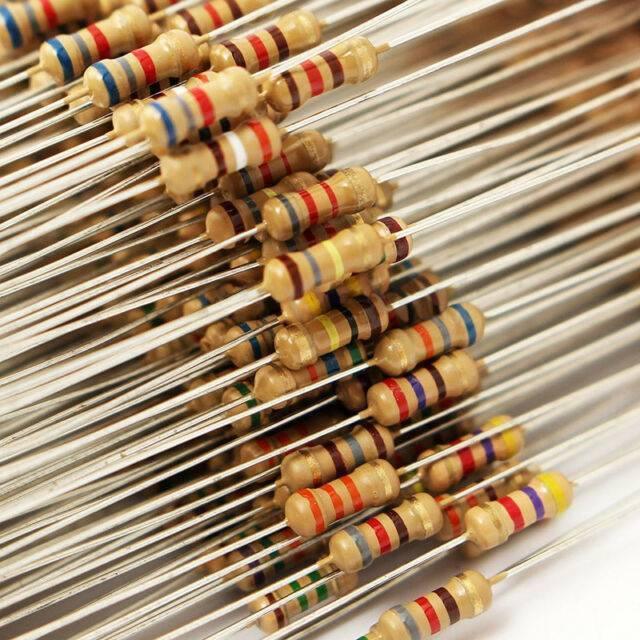
Resistors are electronic components that have a specific, never-changing electrical resistance. The resistor’s resistance limits the flow of electrons through a circuit.
They are passive components, meaning they only consume power (and can’t generate it). Resistors are usually added to circuits where they complement active components like op-amps, microcontrollers, and other integrated circuits. Common resistors are used to limit current, divide voltages, and pull up I/O lines.
Resistor units
The electrical resistance of a resistor is measured in ohms. The symbol for an ohm is the greek capital-omega: Ω. The (somewhat roundabout) definition of 1Ω is the resistance between two points where 1 volt (1V) of applied potential energy will push 1 ampere (1A) of current.
As SI units go, larger or smaller values of ohms can be matched with a prefix like a kilo-, mega-, or giga-, to make large values easier to read. It’s very common to see resistors in the kilohm (kΩ) and megaohm (MΩ) range (much less common to see milliohm (mΩ) resistors).
For example, a 4,700Ω resistor is equivalent to a 4.7kΩ resistor, and a 5,600,000Ω resistor can be written as 5,600kΩ or (more commonly as) 5.6MΩ.
Schematic symbol
All resistors have two terminals, one connection on each end of the resistor. When modeled on a schematic, a resistor will show up as one of these two symbols:
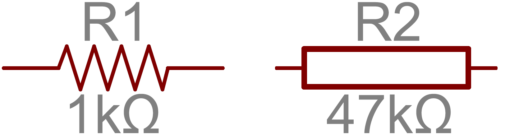
Two common resistor schematic symbols. R1 is an American-style 1kΩ resistor, and R2 is an international-style 47kΩ resistor.
The terminals of the resistor are each of the lines extending from the squiggle (or rectangle). Those are what connect to the rest of the circuit.
The resistor circuit symbols are usually enhanced with both a resistance value and a name. The value, displayed in ohms, is critical for both evaluating and constructing the circuit. The name of the resistor is usually an R preceding a number. Each resistor in a circuit should have a unique name/number. For example, here are a few resistors in action on a 555 timer circuit:
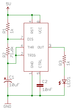
In this circuit, resistors play a key role in setting the frequency of the 555 timer’s output. Another resistor (R3) limits the current through an LED.
Types of Resistors
Resistors come in a variety of shapes and sizes. They might be through-hole or surface-mount. They might be a standard, static resistor, a pack of resistors, or a special variable resistor.
Termination and mounting
Resistors will come in one of two termination types: through-hole or surface-mount. These types of resistors are usually abbreviated as either PTH (plated through-hole) or SMD/SMT (surface-mount technology or device).
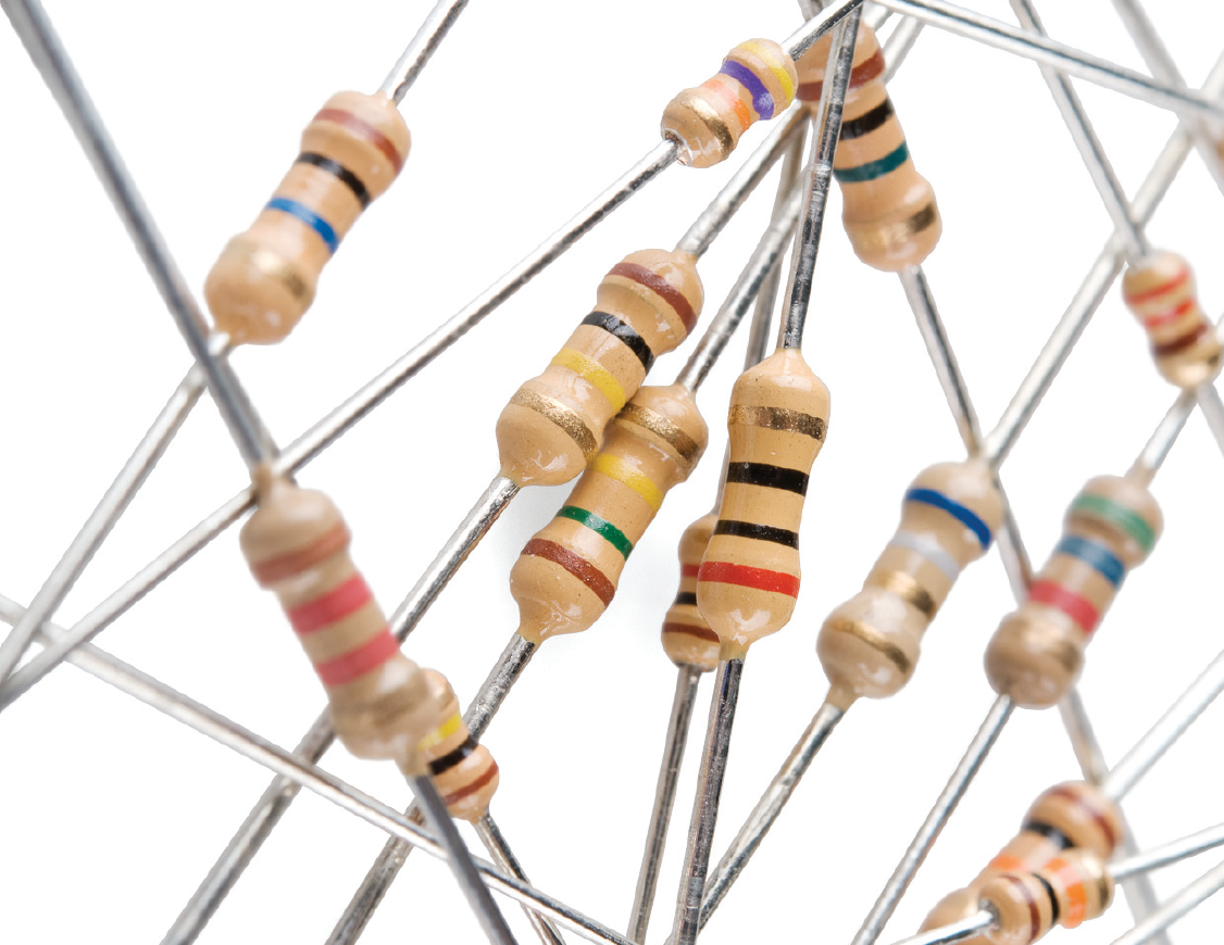
Through-hole resistors come with long, pliable leads which can be stuck into a breadboard or hand-soldered into a prototyping board or printed circuit board (PCB). These resistors are usually more useful in breadboarding, prototyping, or in any case where you’d rather not solder tiny, little 0.6mm-long SMD resistors. The long leads usually require trimming, and these resistors are bound to take up much more space than their surface-mount counterparts.
The most common through-hole resistors come in an axial package. The size of an axial resistor is relative to its power rating. A common ½W resistor measures about 9.2mm across, while a smaller ¼W resistor is about 6.3mm long.
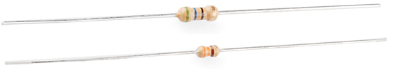
A half-watt (½W) resistor (above) sized up to a quarter-watt (¼W).
Surface-mount
resistors are usually tiny black rectangles, terminated on either side with even smaller, shiny, silver, conductive edges. These resistors are intended to sit on top of PCBs, where they’re soldered onto mating landing pads. Because these resistors are so small, they’re usually set into place by a robot and sent through an oven where solder melts and holds them in place.

A tiny 0603 330Ω resistor hovering over shiny George Washington’s nose on top of a U.S. quarter.
SMD resistors come in standardized sizes; usually either 0805 (0.8mm long by 0.5mm wide), 0603, or 0402. They’re great for mass circuit-board-production, or in designs where space is a precious commodity. They take a steady, precise hand to manually solder, though!
Resistor composition
Resistors can be constructed out of a variety of materials. Most common, modern resistors are made out of either carbon, metal, or metal-oxide film. In these resistors, a thin film of conductive (though still resistive) material is wrapped in a helix around and covered by an insulating material. Most of the standard, no-frills, through-hole resistors will come in a carbon-film or metal-film composition.
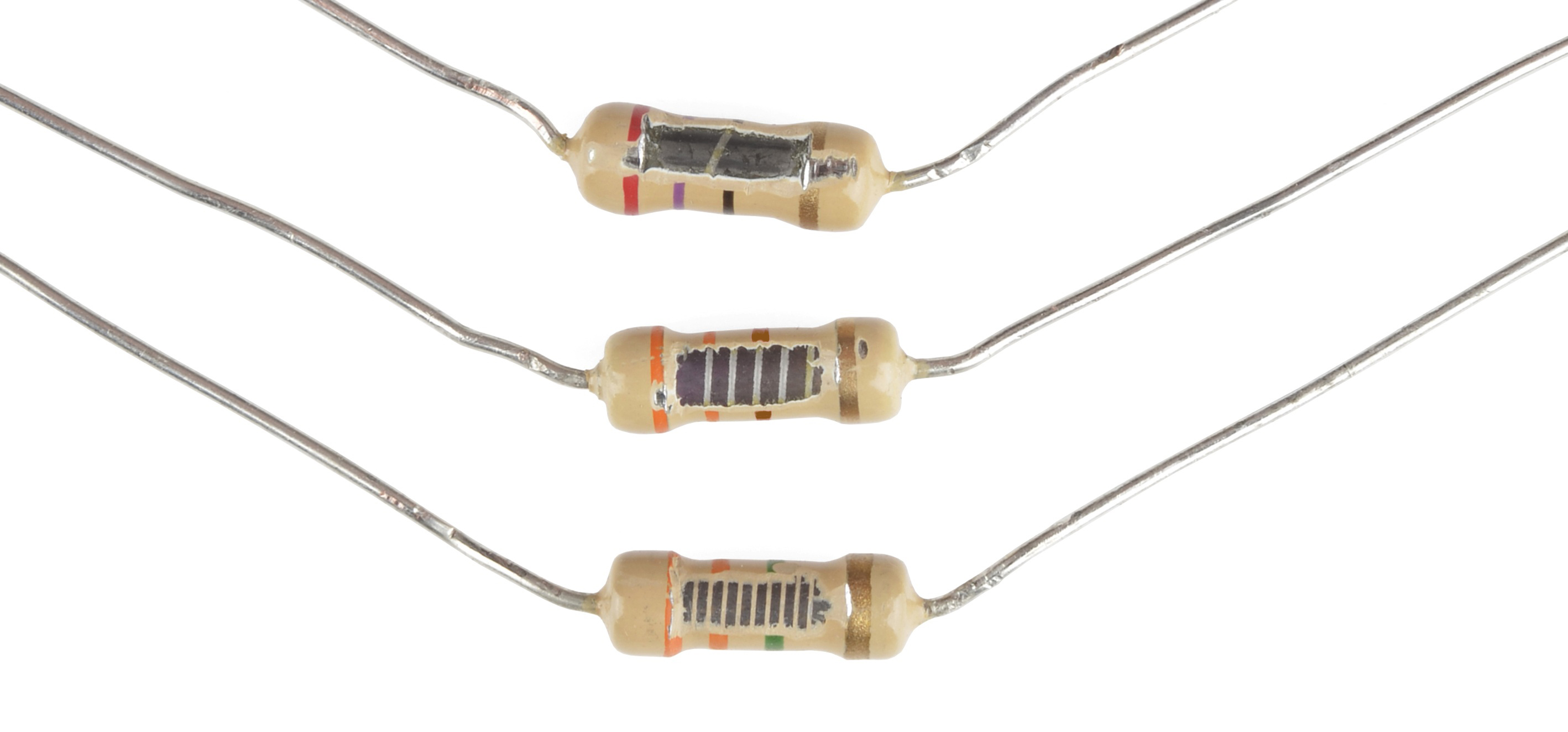
Peek inside the guts of a few carbon-film resistors. Resistance values from top to bottom: 27Ω, 330Ω, and 3.3MΩ. Inside the resistor, a carbon film is wrapped around an insulator. More wraps mean a higher resistance. Pretty neat!
Other through-hole resistors might be wirewound or made of a super-thin metallic foil. These resistors are usually more expensive, higher-end components specifically chosen for their unique characteristics like a higher power rating, or maximum temperature range.
Surface-mount resistors are usually either thick or thin-film varieties. Thick-film is usually cheaper but less precise than thin. In both resistor types, a small film of resistive metal alloy is sandwiched between a ceramic base and glass/epoxy coating and then connected to the terminating conductive edges.
Special resistor packages
There are a variety of other, special-purpose resistors out there. Resistors may come in pre-wired packs of five-or-so resistor arrays. Resistors in these arrays may share a common pin, or be set up as voltage dividers.
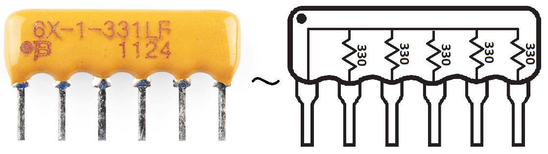
An array of five 330Ω resistors, all tied together at one end.
Resistors don’t have to be static either. Variable resistors, known as rheostats, are resistors that can be adjusted between a specific range of values. Similar to the rheostat is the potentiometer. Pots connect two resistors internally, in series, and adjust a center tap between them creating an adjustable voltage divider. These variable resistors are often used for inputs, like volume knobs, which need to be adjustable.
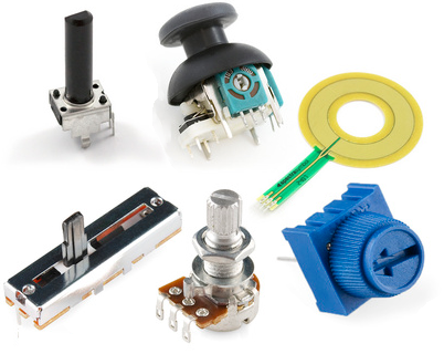
A smattering of potentiometers. From top-left, clockwise: a standard 10k trimpot, 2-axis joystick, soft pot, slide pot, classic right-angle, and a breadboard-friendly 10k trimpot.
Resistor Pack Of 15 Values Decoding Resistor Markings:
Though they may not display their value outright, most resistors are marked to show what their resistance is. PTH resistors use a color-coding system (which adds some flair to circuits), and SMD resistors have their value-marking system.
Decoding the color bands
Through-hole, axial resistors usually use the color-band system to display their value. Most of these resistors will have four bands of color circling the resistor.
The first two bands indicate the two most-significant digits of the resistor’s value. The third band is a weight value, which multiplies the two significant digits by a power of ten.
The final band indicates the tolerance of the resistor. The tolerance explains how much more or less the actual resistance of the resistor can be compared to what its nominal value is. No resistor is made to perfection, and different manufacturing processes will result in better or worse tolerances. For example, a 1kΩ resistor with 5% tolerance could be anywhere between 0.95kΩ and 1.05kΩ.
How do you tell which band is first and last? The last, tolerance band is often clearly separated from the value bands, and usually, it’ll either be silver or gold.
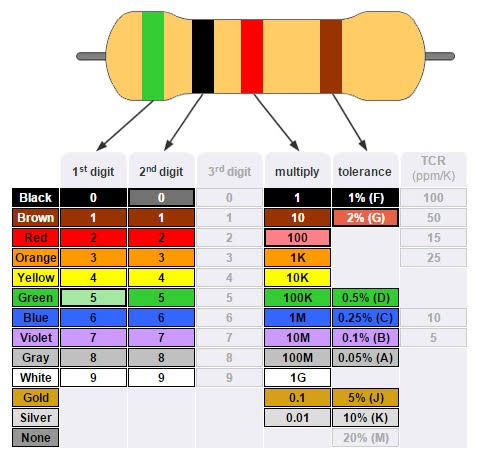
Here’s a table of each of the colors and which value, multiplier, or tolerance they represent:
| Color | Digit value | Multiplier | Multiplied Out | Tolerance |
| Black | 0 | 100 | 1 | |
| Brown | 1 | 101 | 10 | |
| Red | 2 | 102 | 100 | |
| Orange | 3 | 103 | 1,000 | |
| Yellow | 4 | 104 | 10000 | |
| Green | 5 | 105 | 100,000 | |
| Blue | 6 | 106 | 1,000,000 | |
| Violet | 7 | 107 | 10,000,000 | |
| Gray | 8 | 108 | 100,000,000 | |
| White | 9 | 109 | 1,000,000,000 | |
| Gold | ±5% | |||
| Silver | ±10% |
Here’s an example of a 4.7kΩ resistor with four color bands:
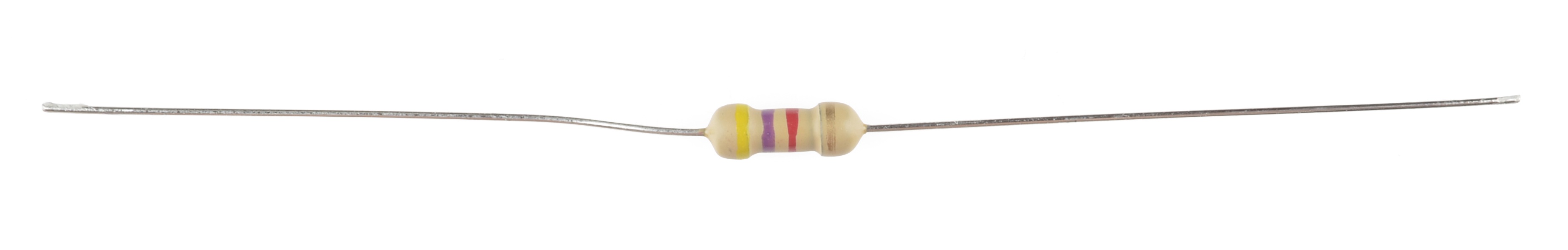
When decoding the resistor color bands, consult a resistor color code table like the one above. For the first two bands, find that color’s corresponding digit value.
Hence the 4.7kΩ resistor has color bands of yellow and violet to begin – which have digit values of 4 and 7 (47). The third band of the 4.7kΩ is red, which indicates that the 47 should be multiplied by 102 (or 100). 47 times 100 is 4,700!
If you’re trying to commit the color band code to memory, a mnemonic device might help. There are a handful of(sometimes unsavory) mnemonics out there, to help remember the resistor color code. A good one, which spells out the difference between black and brown is:
“Big brown rabbits often yield great big vocal groans when gingerly snapped.”
Or, if you remember “ROY G. BIV”, subtract the indigo (poor indigo, no one remembers indigo), and add black and brown to the front and gray and white to the back of the classic rainbow color order.
Resistor Pack Of 15 Values Color Code Calculator
If you’d rather skip the math (we won’t judge :), and just use a handy calculator, give this a try!
| Band 1 | Band 2 | Band 3 | Band 4 | |
| Value 1 (MSV) | Value 2 | Weight | Tolerance | |
| Black (0) Brown (1) Red (2) Orange (3) Yellow (4) Green (5) Blue (6) Violet (7) Gray (8) White (9) |
Black (0) Brown (1) Red (2) Orange (3) Yellow (4) Green (5) Blue (6) Violet (7) Gray (8) White (9) |
Black (1) Brown (10) Red (100) Orange (1k) Yellow (10k) Green (100k) Blue (1M) Violet (10M) Gray (100M) White (1G) |
Gold (± 5%) Silver (± 10%) |
|
Resistance: |
1,000 Ω ±5% |
|||
Decoding surface-mount markings
SMD resistors, like those in 0603 or 0805 packages, have their way of displaying their value. There are a few common marking methods you’ll see on these resistors. They’ll usually have three to four characters – numbers or letters – printed on top of the case.
If the three characters you’re seeing are all numbers, you’re probably looking at an E24 marked resistor. These markings share some similarities with the color-band system used on the PTH resistors. The first two numbers represent the first two most-significant digits of the value, the last number represents a magnitude.
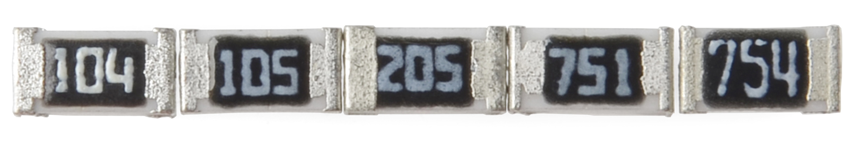
In the above example picture, resistors are marked 104, 105, 205, 751, and 754. The resistor marked with 104 should be 100kΩ (10×104), 105 would be 1MΩ (10×105), and 205 is 2MΩ (20×105). 751 is 750Ω (75×101), and 754 is 750kΩ (75×104).
Another common coding system is E96, and it’s the most cryptic of the bunch. E96 resistors will be marked with three characters – two numbers at the beginning and a letter at the end. The two numbers tell you the first three digits of the value, by corresponding to one of the not-so-obvious values on this lookup table.
Table :
| Code | Value | Code | Value | Code | Value | Code | Value | Code | Value | Code | Value | |||||
|---|---|---|---|---|---|---|---|---|---|---|---|---|---|---|---|---|
| 01 | 100 | 17 | 147 | 33 | 215 | 49 | 316 | 65 | 464 | 81 | 681 | |||||
| 02 | 102 | 18 | 150 | 34 | 221 | 50 | 324 | 66 | 475 | 82 | 698 | |||||
| 03 | 105 | 19 | 154 | 35 | 226 | 51 | 332 | 67 | 487 | 83 | 715 | |||||
| 04 | 107 | 20 | 158 | 36 | 232 | 52 | 340 | 68 | 499 | 84 | 732 | |||||
| 05 | 110 | 21 | 162 | 37 | 237 | 53 | 348 | 69 | 511 | 85 | 750 | |||||
| 06 | 113 | 22 | 165 | 38 | 243 | 54 | 357 | 70 | 523 | 86 | 768 | |||||
| 07 | 115 | 23 | 169 | 39 | 249 | 55 | 365 | 71 | 536 | 87 | 787 | |||||
| 08 | 118 | 24 | 174 | 40 | 255 | 56 | 374 | 72 | 549 | 88 | 806 | |||||
| 09 | 121 | 25 | 178 | 41 | 261 | 57 | 383 | 73 | 562 | 89 | 825 | |||||
| 10 | 124 | 26 | 182 | 42 | 267 | 58 | 392 | 74 | 576 | 90 | 845 | |||||
| 11 | 127 | 27 | 187 | 43 | 274 | 59 | 402 | 75 | 590 | 91 | 866 | |||||
| 12 | 130 | 28 | 191 | 44 | 280 | 60 | 412 | 76 | 604 | 92 | 887 | |||||
| 13 | 133 | 29 | 196 | 45 | 287 | 61 | 422 | 77 | 619 | 93 | 909 | |||||
| 14 | 137 | 30 | 200 | 46 | 294 | 62 | 432 | 78 | 634 | 94 | 931 | |||||
| 15 | 140 | 31 | 205 | 47 | 301 | 63 | 442 | 79 | 649 | 95 | 953 | |||||
| 16 | 143 | 32 | 210 | 48 | 309 | 64 | 453 | 80 | 665 | 96 | 976 |
The letter at the end represents a multiplier, matching up to something on this table:
| Letter | Multiplier | Letter | Multiplier | Letter | Multiplier | ||
|---|---|---|---|---|---|---|---|
| Z | 0.001 | A | 1 | D | 1000 | ||
| Y or R | 0.01 | B or H | 10 | E | 10000 | ||
| X or S | 0.1 | C | 100 | F | 100000 |
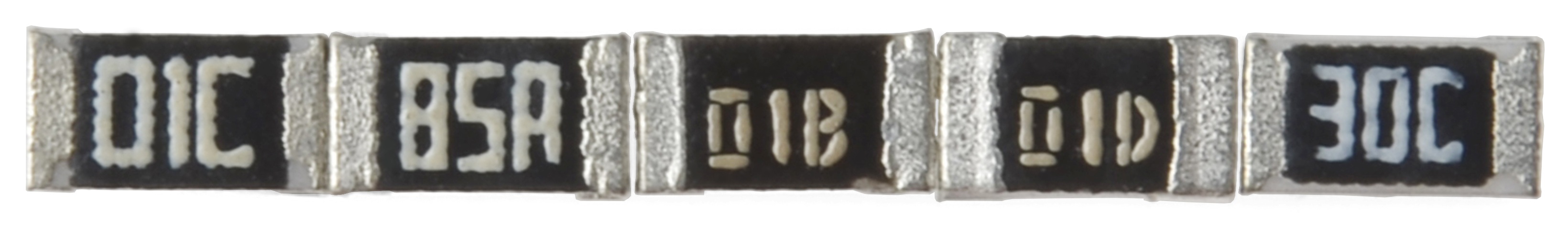
So a 01C resistor is our good friend, 10kΩ (100×100), 01B is 1kΩ (100×10), and 01D is 100kΩ. Those are easy, other codes may not be. 85A from the picture above is 750Ω (750×1) and 30C is 20kΩ.
Power Rating
The power rating of a resistor is one of the more hidden values. Nevertheless, it can be important, and it’s a topic that’ll come up when selecting a resistor type.
Power is the rate at which energy is transformed into something else. It’s calculated by multiplying the voltage difference across two points by the current running between them and is measured in units of a watt (W).
Light bulbs, for example, power electricity into light. But a resistor can only turn electrical energy running through it into heat. Heat isn’t usually a nice playmate with electronics; too much heat leads to smoke, sparks, and fire!
Every resistor has a specific maximum power rating. To keep the resistor from heating up too much, so it’s important to make sure the power across a resistor is kept under its maximum rating.
In addition the power rating of a resistor is measured in watts, and it’s usually somewhere between ⅛W (0.125W) and 1W. Resistors with power ratings of more than 1W are usually referred to as power resistors and are used specifically for their power dissipating abilities.
Finding a resistor’s power rating
A resistor’s power rating can usually be deduced by observing its package size. Standard through-hole resistors usually come with ¼W or ½W ratings. More special purpose, power resistors might list their power rating on the resistor.
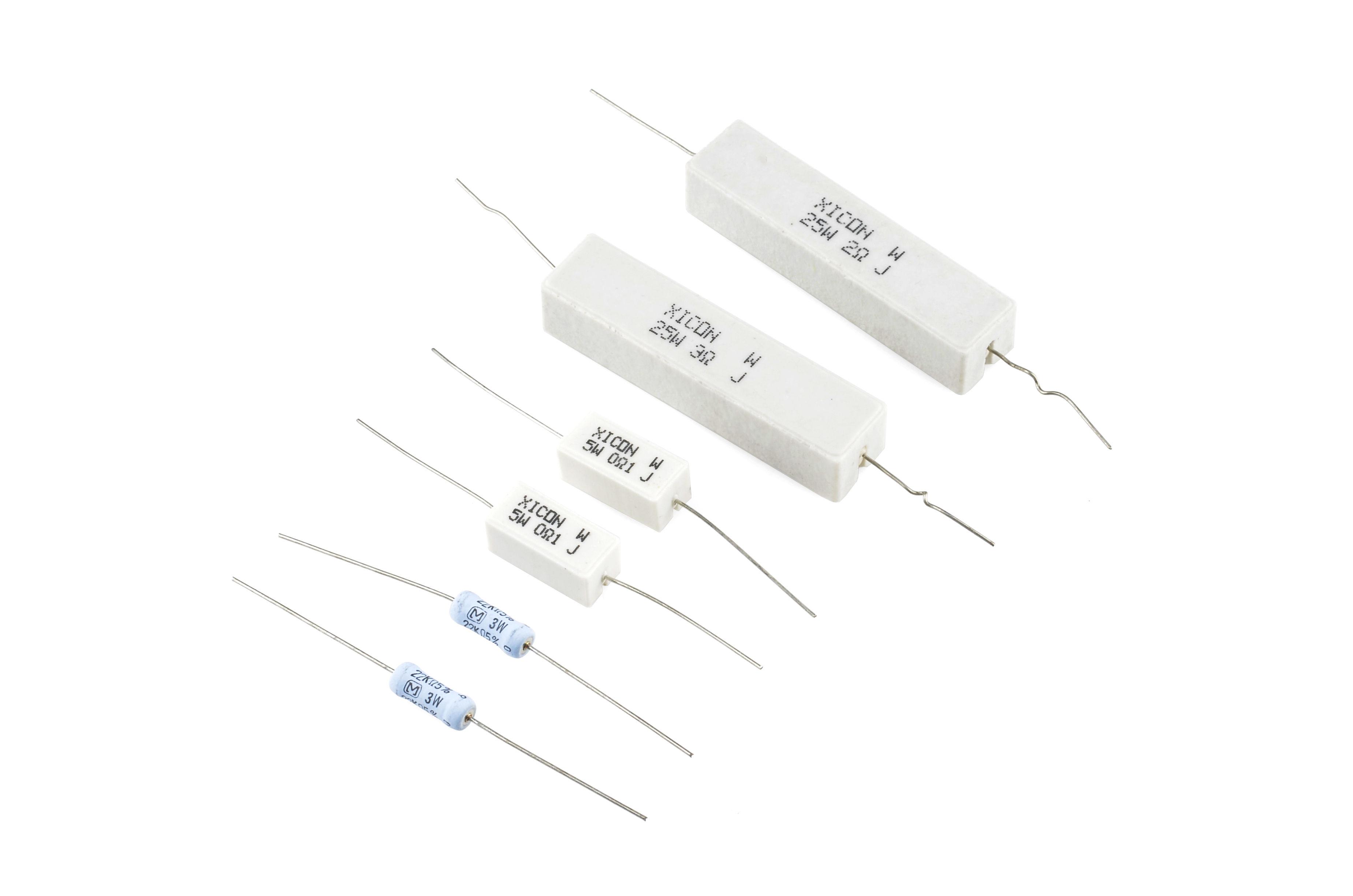
These power resistors can handle a lot more power before they blow. From top-right to bottom-left there are examples of 25W, 5W and 3W resistors, with values of 2Ω, 3Ω 0.1Ω and 22kΩ. Smaller power-resistors are often used to sense current.
The power ratings of surface mount resistors can usually be judged by their size as well. Both 0402 and 0603-size resistors are usually rated for 1/16W, and 0805’s can take 1/10W.
Measuring power across a resistor
Power is usually calculated by multiplying voltage and current (P = IV). But, by applying Ohm’s law, we can also use the resistance value in calculating power. If we know the current running through a resistor, we can calculate the power as:

Or, if we know the voltage across a resistor, the power can be calculated as:
 Package includes :
1 x 150pcs Resistor Pack Of 15 Values 10r,47r,100r,220r,330r,470r,1k,2.2k,4.7k,6.8k,10k,22k,47k,100k,220k