Pic Lab-iii Microchip Pic Microcontroller Development Board
Guaranteed Safe Checkout

Pic Lab-iii Microchip Pic Microcontroller Development Board
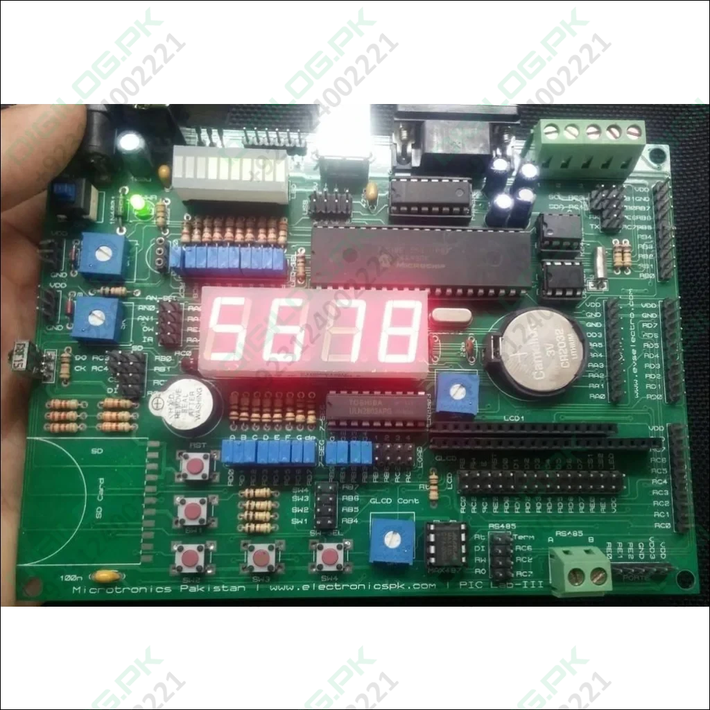
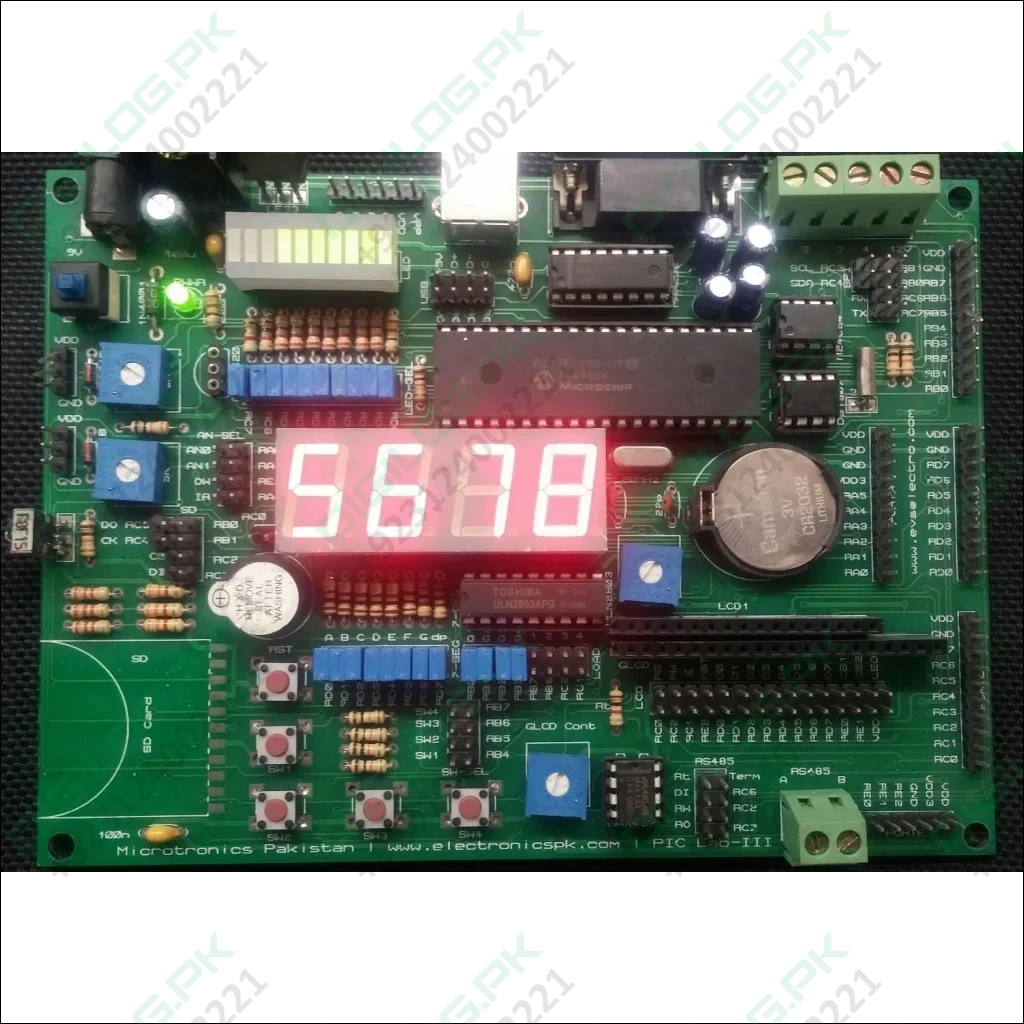
PIC Lab-III is the ultimate in Microchip PIC development boards. This board has full support for Mirochip PIC18F4550 microcontroller and its USB features. Using this you can make all sorts of USB devices like mass storage device, mouse, keyboard and communication etc.
The board can be powered from USB or external 9-12 V DC adapter. PIC Lab-III contains a large number of peripheral modules that are commonly required in project development. Most importantly the modules are not hard-wired to microcontroller, instead you can connect them to our choice of I-Os using simple jumpers, or to I-Os of your choice using jumper cables.
Documentation:
Example Code:
Features:
- Supports all Microchip PIC 40 pin PIC microcontrollers ( 18F4550 is preferred)
- USB 2.0 support circuitry for PIC 18F4550 Microcontroller
- USART with MAX232 serial communication
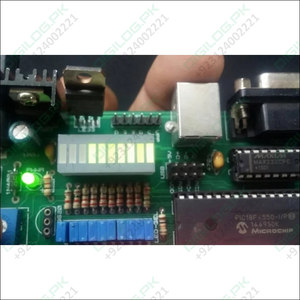
- 10 status LEDs
- 4 user programmable push switches
- SD card holder for massive data storage
- 2 ADC ports with POT as voltage divider and 5.1V zener protection, one of the channels can be connected as reference volts
- Buzzer
- 38KHz IR remote control sensor
- One wire Dalas protocol (DS1820) temperature sensor network
- HD44780 Character LCD interface, both 4bit and 8 bit modes supported
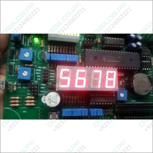
- 4 seven segment multiplexed LED digits
- 4 channels of heavy DC load for external relays, solenoids, steppers (upto 500mA per channel)
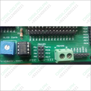
- RS 485 network configurable as node and terminal
- KS0108 Graphic LCD interface
- I2C EEPROM (24C08 … 24C512 supported)
- I2C DS1307 Real time clock and calendar with battery backup
- In circuit programming header as per Microchip standard for connection withPICkit-2, ICD-2 etc.
- All I-O lines available as headers grouped as PORTS along with 5V DC supply
- on-board 3.3V regulator (up to 1A) output available through two headers
PIC Lab-III Introduction
Microchip PIC micro-controllers are fun to learn and use. Many students and hobbyists enjoy making the circuit on breadboard. PIC Lab-III is a state of the PIC development board, that can be used to develop and test a new project or learn to use various devices.
The board supports all 40 pin PIC microcontrollers, however I prefer using it with PIC18F4550. This microcontroller has built-in USB 2.0 module which is a great support to help develop USB based applications and devices.
The board has a large number of commonly used devices per-fabricated, with connection headers to connect the device to I-O lines of your choice. For example we have 10 LED s to indicate status etc, in your application. These are not hard wired to any I-O line, rather there is a two row header, with LED connections on one side and controller I-O lines that we suggest to be used on other row, like RD0 to RD7 and C6, C7. If you want to accept this configuration just put a short jumper and LED is connected to corresponding I-O pin. If lets say you want to connect the LED to RE0, just unplug the shortening jumper and using a standard female to female connector wire connect the LED pin to RE0 pin on I-O headers available on board. This makes this board 100% reconfigurable according to your choice.
This is the situation with all devices on board. on top of that the I-Os are also available from headers for easy interfacing with extra hardware that you can make on breadboard or strip-board.
Customer questions & answers
Ask a question
No questions yet. Be the first to ask!

