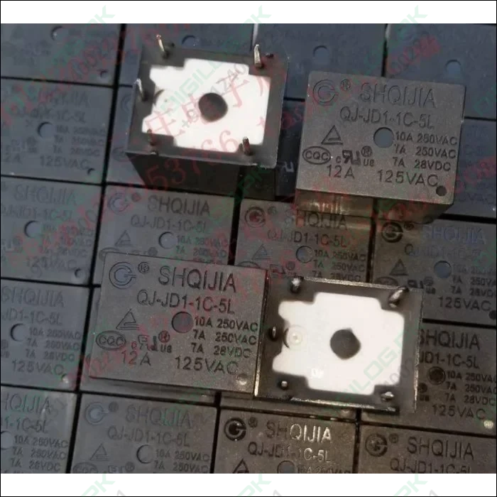
Dc 5volt 5pin Relay Spdt
Guaranteed Safe Checkout
Relay is one kind of electro-mechanical component that functions as a switch. The relay coil is energized by DC so that contact switches can be opened or closed. A single channel 5V relay module generally includes a coil, and two contacts like normally open (NO) and normally closed (NC). This article discusses an overview of the 5V relay module & its working but before going to discuss what is relay module is, first we have to know what is relay and its pin configuration.
What is a 5V Relay?
A 5v relay is an automatic switch that is commonly used in an automatic control circuit and to control a high-current using a low-current signal. The input voltage of the relay signal ranges from 0 to 5V.
5V Relay Pin Configuration
The pin configuration of the 5V relay is shown below. This relay includes 5-pins where each pin and its functionality are shown below.
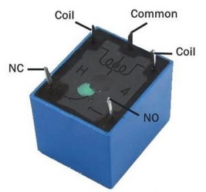
Pin1 (End 1): It is used to activate the relay; usually this pin one end is connected to 5Volts whereas another end is connected to the ground.
Pin2 (End 2): This pin is used to activate the Relay.
Pin3 (Common (COM)): This pin is connected to the main terminal of the Load to make it active.
Pin4 (Normally Closed (NC)): This second terminal of the load is connected to either NC/ NO pins. If this pin is connected to the load then it will be ON before the switch.
Pin5 (Normally Open (NO)): If the second terminal of the load is allied to the NO pin, then the load will be turned off before the switch.
Features
The features of the 5V relay include the following.
- Normal Voltage is 5V DC
- Normal Current is 70mA
- AC load current Max is 10A at 250VAC or 125V AC
- DC load current Max is 10A at 30V DC or 28V DC
- It includes 5-pins & designed with plastic material
- Operating time is 10msec
- Release time is 5msec
- Maximum switching is 300 operating per minute
5V Relay Module
The relay module with a single channel board is used to manage high voltage, current loads like solenoid valves, motor, AC load & lamps. This module is mainly designed to interface through different microcontrollers like PIC, Arduino, etc.
5V Relay Module Pin Configuration
The pin configuration of the 5V relay module is shown below. This module includes 6-pins where each pin and its functionality are discussed below.
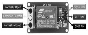
Normally Open (NO): This pin is normally open unless we provide a signal to the relay modules signal pin. So, the common contact pin smashes its link through the NC pin to make a connection through the NO pin
Common Contact: This pin is used to connect through the load that we desire to switch by using the module.
Normally Closed (NC): This NC pin is connected through the COM pin to form a closed circuit. However, this NC connection will break once the relay is switched through providing an active high/low signal toward the signal pin from a microcontroller.
Signal Pin: The signal pin is mainly used for controlling the relay. This pin works in two cases like active low otherwise active high. So, in active low case, the relay activates once we provide an active low signal toward the signal pin, whereas, in an active high case, the relay will trigger once we provide a high signal toward the signal pin.
However, these modules generally work on an active high signal which will strengthen the relay coil to make contact with the common terminal with the normally open terminal.
5V VCC: This pin needs 5V DC to work. So 5V DC power supply is provided to this pin.
Ground: This pin connects the GND terminal of the power supply.
5Volts 1-Channel Relay Module Components
The components in a 5v relay module with a single channel include a relay, output terminal, status LED, power LED, freewheeling diode, input connector & switching transistor.
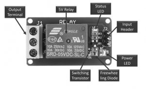
Relay
A 5V relay is coated with blue color plastic material. For both AC & DC loads, the utmost operating voltage & current are also displayed on the relay. This relay operates with 5V, so it is called a 5V relay.
Output Terminal
The output terminal of the relay module is located at the left-hand side, used to fix an AC/DC load & AC/DC i/p power source. Every o/p connector’s terminal is connected through NC, COM pins & NO of the relay.
The relay module consists of screws that are used to connect wires & cables. The max current supported by this module is 10A & the max contact voltage is 250V AC & 30V DC. Thick main cables are mainly used whenever high voltage & current load is used.
Status LED
Status LED is connected by using a current limiting resistor that is located on the top right side of the relay module. So this LED illustrates the relay status by activating the relay & coil through a signal pin. The DC supplies throughout a relay coil.
Power LED
Power LED shows the condition of the power source that is connected through the single channel module. If we provide the above 5V source toward both the pins of the module like Vcc & GND, the LED will be damaged due to high voltage.
Freewheeling Diode
The connection of this diode can be done across the coil to keep away from the back EMF effect, so-called a flyback diode. The type of coil used in the relay is the inductive type. Once the current supplies throughout an inductive load, then it generates a back EMF voltage, which may harm the circuit. So, this diode is mainly used to keep away from this effect.
Input Connector
The input connector is located on the right side of the module. This connector is mainly used to supply a 5V power supply & input signal. In addition, it also supplies power supply toward the power LED, relay coil & status LED.
Switching Transistor
Generally, the input signal which is given to a relay is from the I/O pins of microcontrollers like ESP32, TM4C123, Arduino, etc. However, the highest current sourcing capacity of GPIO pins is usually below 20mA.
Therefore, a switching transistor is used in this module is to strengthen the current to the requirement of the minimum current level of the relay coil. A switching transistor is used to control the 5V relay from the microcontroller’s GPIO pin.
Some kinds of relay modules are available with an optoisolator like a switching device to give optical isolation among high & low voltage circuits.
However, if you are utilizing a separate relay exclusive of a module & you want to utilize several relays within your projects, then a relay driver IC can be used to drive several arrays from the pins of GPIO in a microcontroller.
Specifications
The specifications of a 1- channel relay module include the following.
- Voltage supply ranges from 3.75V – 6V
- Quiescent current is 2mA
- Once the relay is active then the current is ~70mA
- The highest contact voltage of a relay is 250VAC/30VDC
- The maximum current is 10A
Working
The relay uses the current supply for opening or closing switch contacts. Usually, this can be done through a coil to magnetize the switch contacts & drags them jointly once activated. A spring drives them separately once the coil is not strengthened.
By using this system, there are mainly two benefits, the first one is, the required current for activating the relay is less as compared to the current used by relay contacts for switching. The other benefit is, both the contacts & the coil are isolated galvanically, which means there is no electrical connection among them.
How to Use/Relay Module Circuit Diagram
The circuit diagram of the single-channel relay module circuit is shown below. In this circuit, we can observe that how the relay module is activated and deactivated through a digital signal. This signal is applied to a control pin of the relay module. The following circuit diagram is the internal 5V single channel relay module diagram.
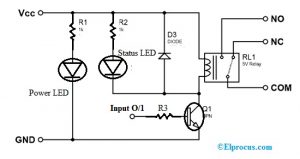
In the above circuit diagram, the single-channel relay module includes resistors-2, transistors, LEDs-2 & a 5V relay. Relay modules are available in two types based on the control signal type used for activation of the relay.
One relay module comes with an NPN transistor whereas another module comes with a PNP transistor. If the relay module uses an NPN Transistor, then it will activate the relay by applying an active high signal to the control pin. Alternatively, if a PNP is used then the relay will be activated through an active low signal on the control pin.
It’s working in proteus simulation software is, when we provide an active high signal toward the control pin in a relay module, then the coil in the relay activates to make the relay active through the connection of the NO pin through the COM pin.
Likewise, once we provide an active low no signal toward the relay’s control pin, then the coil deactivates using a freewheeling diode so that the relay will be deactivated.
In the same way, for PNP based relay module, the relay is activated through an active low signal, whereas an active high signal will deactivate the relay.
The controlling of a 5v single channel relay module can be done by interfacing any kind of microcontroller. For that, we use a GPIO pin like a digital o/p pin which gives an active high & low signal toward the control pin. Once the relay activates, we can listen to an audible sound that comes from the module.
Advantages
The advantages of the relay module include the following.
- A remote device can be controlled easily
- It is triggered with less current but it can also trigger high power machines
- Easily contacts can be changed
- At a time, several contacts can be controlled using a single signal
- Activating part can be isolated
- It can switch AC or DC
- At high temperatures, it works very well
Disadvantages
The disadvantages of the relay module include the following.
- When contacts of relay modules are used overtime then they may damage
- Noise can be generated through the opening & closing of the contacts.
- Time taken for switching is High
Applications
Relay modules are used in different applications which include the following.
- Used in over voltage/under voltage protection system
- Mains Switching
- Speed control of motors through start-delta converters
- Automatic electrical appliances
- Electrical isolation in between high & low power sources
- Lights
- AC voltage load switching using less voltage DC
- Delivery of Isolated power
- Home automation projects
- Switching with High Current
Customer questions & answers
Ask a question
No questions yet. Be the first to ask!
