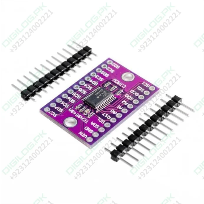
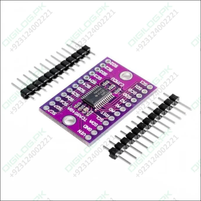
Cjmcu-9548 Tca9548a 1-to-8 I2c 8-channel Iic Multiplexer Multi-channel Expansion Development Board For Arduino
Guaranteed Safe Checkout


Cjmcu-9548 Tca9548a 1-to-8 I2c 8-channel Iic Multiplexer Multi-channel Expansion Development Board For Arduino
You just found the perfect I2C sensor, and you want to wire up two, three, or more of them to your Arduino. When you realize “Oh no, this chip has a fixed I2C address, and from what I know about I2C; you cannot have two devices with the same address on the same SDA/SCL pins”. Are you out of luck? You would be if you don’t have this cool CJMCU TCA9548A I2C 8 Channel Multiple extensions development board.
The CJMCU TCA9548A I2C 8 Channel Multiple extensions development board is interesting in that it has an I2C address (0x70 by default) – and you basically send it a command to tell it which I2C multiplexed output you want to talk to, then you can address the board you want to address.
Robu.in have a different kind of breakout boards; for more boards Click here.
Specification and Features :
- 1-to-8 Bidirectional Translating Switches.
- Supports Hot Insertion.
- Low Standby Current.
- 1-to-8 Bidirectional Translating Switches.
- Active-Low Reset Input.
- Power Up With All Switch Channels Deselected.
- I2C Bus and SMBus Compatible.
- 5-V Tolerant Inputs.
- Latch-Up Performance Exceeds 100 mA Per JESD 78, Class II.
Pin Description :
Power Pins:
- Vin – this is the power pin. Since the sensor chip uses 3-5 VDC. To power, the board, give it the same power as the logic level of your microcontroller – e.g. for a 5V micro like Arduino, use 5V.
- GND – common ground for power and logic.
I2C Control-Side pins :
- SCL – this is the I2C clock pin for the chip itself, connect to your microcontrollers I2C clock line.
- SDA – this is the I2C data pin for the chip itself, connect to your microcontrollers I2C data line.
- RST – this is the reset pin, for resetting the multiplexer chip. Pulled high by default, connect to ground to reset
- A0 A1 A2 – these are the address selection pins for the multiplexer. By default, the multiplexer is at address 0x70 and these three pins are pulled low. Connect them to Vin to set the address to 0x71 – 0x77.
- A0 is the lowest-significant bit (if it is pulled high, it will increase the address by 1).
- A1 is the 2nd-lowest-significant bit (if it is pulled high, it will increase the address by 2).
- A2 is the 3rd-lowest-significant bit (if it is pulled high, it will increase the address by 4).
I2C Multiplexed-Side pins:
- SDx and SCx: There are 8 sets of SDx and SCx pins, from SD0/SC0 to SD7/SC7. These are the multiplexed pins. Each one is a completely separate I2C bus set. So you have 8 I2C devices with identical addresses, as long as they are on one I2C bus each.
- These pins do not have any pullups installed, so if you are using a chip or breakout without I2C pull-ups be sure to add them! Nicely, you can have Vin be 3.3V and have these pins pulled up to 5V (that is, they are 5V compliant).
Program :
We suggest using this little helper to help you select the port
#define TCAADDR 0x70
void tcaselect(uint8_t i) {
if (i > 7) return;
Wire.beginTransmission(TCAADDR);
Wire.write(1 << i);
Wire.endTransmission();
}
You can then call tcaselect(0) thru tcaselect(7) to set up the multiplexer.
Note that you if you happen to have I2C devices with I2C address 0x70, you will need to short one of the Addr pins on the TCA9548 breakout to Vin in order to make it not conflict. Given that you can have 0x70 thru 0x77, just find one that’s free and you’re good to go.
Package Includes :
1 x CJMCU TCA9548A I2C 8 Channel Multiple extensions development board.
2 x Header set ( Without Soldered).


