
Simple Logic Probe Circuit Simulation using Op-Amp for Troubleshooting
Hello electronics hobbyists and engineers. Today I am going to share a very useful and simple circuit design for a Logic Probe. If you are working on digital electronics, Arduino, or microcontrollers, you know that checking the logic state (High or Low) is very important.
Sometimes multimeter is not fast enough to show the state, or it is hard to look at screen again and again. A logic probe give you instant visual indication with LEDs if the pin is High (1) or Low (0).
How This Circuit Works
As you can see in the simulation image above which I designed in Proteus, we are using two Op-Amps (Operational Amplifiers). These Op-Amps are working as Comparators. The main idea is to create a "Window Comparator".
We use a voltage divider network with three resistors:
- 13k Resistor
- 8.2k Resistor
- 3.9k Resistor
These resistors create two reference voltages. One reference is around 2.4V and other is around 0.8V. This is designed according to standard TTL Logic levels.
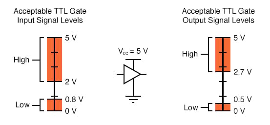
Understanding TTL Logic Levels
In digital electronics, 5V is not always exactly 5V. There is a range.
- Logic High (1): Usually voltage above 2.0V or 2.7V is considered High.
- Logic Low (0): Voltage below 0.8V is considered Low.
- Floating: The area between these voltages is undefined.
Simulation Results
In my simulation screenshot, you can see the input test voltage is set to 3.04V via the potentiometer (RV1). Because 3.04V is higher than the upper reference voltage, the logic state shows the High indication.
If you drop the voltage below 0.7V, the other Op-Amp will turn on, indicating a Low state. This is very simple and cheap tool you can make on prototyping board.
Parts List
You can buy all these components directly from our website Digilog.pk at very best price in Pakistan:
- LM358 or LM324 Op-Amp IC
- Resistors (13k, 8.2k, 3.9k, 1k)
- LEDs (Red and Green)
- Veroboard or Breadboard
I hope this circuit help you in your next project repair. Keep visiting www.digilog.pk for more tutorials and electronic parts.
download simulation file for proteus 8.13 or later versions.![]()


